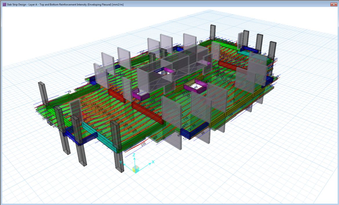
Interpreting the Slab Analysis Result using SAFE program is the last stage to consider in the design of the slab using SAFE. This is the procedure where the structural designer will interpret his/her design and reflect it in a structural plan. A careful and thorough understanding of the output result should be made in order to achieve not only a safe and sound design but also an economical one. In this stage, the designer had a full control of every output or reinforcements that he /she will provide based on the analysis output.
This article discusses how to interpret the Slab Analysis and Design results by CSI SAFE. This is actually related and a continuation of the previous article, Design Strips in CSI SAFE.
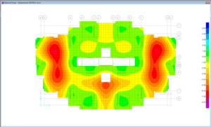
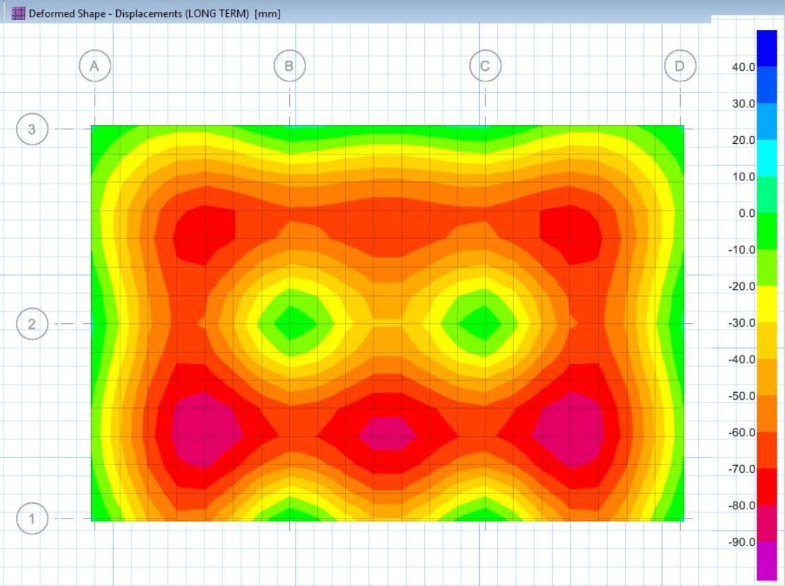
After all the parameters and design strips have been defined, we can now start the analysis and design. But before we proceed further, make sure that the Design Preferences have been set accordingly. We can do that by clicking Design>Design Preferences and from the dialogue box, we can set what code we are going to use and adjust the minimum concrete cover as per the design criteria and specifications. This model is now ready for the analysis. Go to Run>Run Analysis and Design to run the analysis. A Deformed Shape for Displacement will appear after the run analysis and be sure that the deflection under service load combination is not more than L/240 or 24 millimeters. This is, of course, depends on the design criteria and specifications. An example image of the deformed shape of the slab analysis under a service load combination can be seen in the image below.
We can now interpret the output results after we make sure that the deflection is satisfying our project criteria. On the SAFE program interface we go to Display>Show Slab Design or click the Show Slab Design icon and the below form will appear:
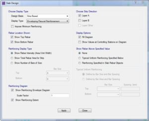
For the purpose of this article, we will base our design basis on a Strip Based. From the Slab Design form, there are three types of reinforcing display available: Show Rebar Intensity, Show Total Rebar Area for Strip and Show Number of Bar of Size. You can use either of the three depending on your convenience. In the Show Rebar Intensity, the recommended area of rebar will display per one-meter width (mm2/m). In Show Total Rebar Area for Strip, the rebar area that will display is the recommended area of rebar according to the width of strips that you provided. In the last type of the reinforcing display is the Show Number of Bars of Size. This is perhaps the most common use option since in this type, the program will display the recommended number of bars and you can play along with the reinforcing mesh that you want to use and adjusts the size and spacing of the extra bars depending on your need. Referring to the three reinforcing display types, during the rebar display interpretation, you can choose to show the Top and Bottom Rebar in either direction separately and display the rebar diagram showing each value.
As a structural designer in-depth knowledge and understanding is required in the design of the slab for us to come up with a safe and sound design. It is important to know and understand the behavior of each of the slabs we are analyzing to achieve convincing design results. It is our obligations and responsibility to make sure that all of this can be done in a proper way and through the aid of CSI SAFE program, every slab we are analyzing from simple to complex is possible.
Acknowledgments: Images on this article was based on CSI SAFE 2016.
Tell us about your thoughts. Leave your message in the comment section below. Feel free to share this article, subscribe to our newsletter and follow us on our social media pages.
[DISPLAY_ACURAX_ICONS]


when we design flat slab for multistories building can we use only two load combination
1.4D
1.4D+1.6L
Yes, we can! The program will consider the worst load combination anyways.
What’s a manual check to verify your results in SAFE for a flat slab design?
Check out these post checks considerations linked here https://www.thestructuralworld.com/2020/02/28/3-post-checks-analysis-and-design-consideration-in-slab-using-csi-safe/
The length of the extra rebar is same as the length shown in the design strip or do we need to ad Ld to the either side of the strip length from SAFE contour
Yes SMM, you need to add the Ld. Cheers!
Thanks for the reply,
Please note that the literature from SAFE manual doesn’t specify this requirement, moreover when we export the rebar details to the drawing using SAFE, it doesn’t add Ld to the rebar extents defined in the Rebar design strip.
Kindly share some literature on this if you have any please.
SMM, not everything is by the book. Our engineering judgment/guts should also be considered in designing. Perhaps consider to detail the reinforcement manually and don’t just rely on the generated SAFE detail reinforcements. The SAFE usually gives the reinforcements according to the results/forces, it doesn’t give you the method on how you will going to lay it in actual construction.
The reinforcement in layer A (as shown in strip design) shall be practically provided along the strip direction or it should be provided across the strip length???
When I add strips and design, it is all good. But in the detailing, the strips have no rebars. It says no rebars. What could be the problem.
And also when designing strips, it sometimes brings a failed error at the bottom corner of the window. What does it mean?
And is the reinforcement provided on top of the A142 wire mesh provided on top of the ribbed slabs?