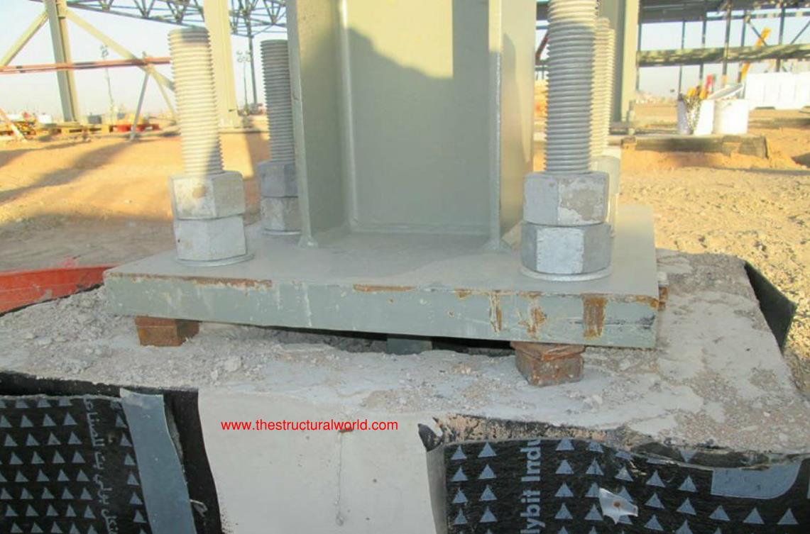
When a column or some instance a beam is subjected for tensile loadings, the said amount of force shall be resisted by anchors, in addition, anchors shall satisfy the required edge distances, spacing, and thicknesses to prevent splitting failure. By definition, an anchor is a steel element either cast into concrete or post-installed into a hardened concrete member and used to transmit applied loads to concrete. In connection with this, the strength or the capacity of anchors shall be checked and design.
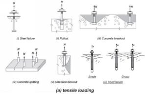
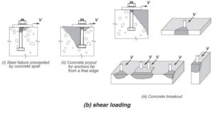
Before we proceed further, it is important to understand the different possible extent of failure if the member is subjected to a huge amount of tensile force. The images below are excerpts from Fig.R17.3.1 of ACI 318M-14 shows the possible failure modes of an anchor in tensile and shear loadings.
To prevent the above failures from happening, anchors should be designed accordingly. In this article, we will dissect the code requirements set forth in Chapter 27 of ACI 318M-14 or Appendix D of ACI 318M-08: Anchoring to Concrete. This is a two-part article for the design considerations on anchoring to concrete. To sum it up, the following are the general requirements for the strength of anchors.
Strength design of anchors shall be check and satisfy the following criteria:
- Tension Loadings
- Steel strength of anchor in tension
- Concrete breakout strength of anchor in tension
- Pull out strength in tension
- Concrete side face blowout strength of headed anchor in tension
- Bond Strength of adhesive anchor in tension
- Shear Loadings
- Steel strength of anchor in shear
- Concrete breakout strength of anchor in shear
- Concrete pry out strength of anchor in shear
Design requirements for tensile loadings:
A. Steel strength of anchor in tension (17.4.1)
The nominal strength of anchor in tension shall not exceed
where:
: effective cross-sectional area (
) of anchor in tension
: smaller of 1.9fya and 125000 psi
B. Concrete breakout strength of anchor in tension (17.4.2)
The nominal concrete breakout strength of anchor in tension shall not exceed:
- For a Single Anchor,
- For a Group of Anchors,
where:
shall not be taken less than:
- 2hef for adhesive anchor
- 2.5hef for undecut anchors
- 4hef for torque controlled expansion anchors
- 4hef for displacement controlled expansion anchors
The basic concrete breakout strength of a single anchor in tension in cracked concrete shall not exceed
where: =24 for cast in anchors and 17 for post-installed anchors
and
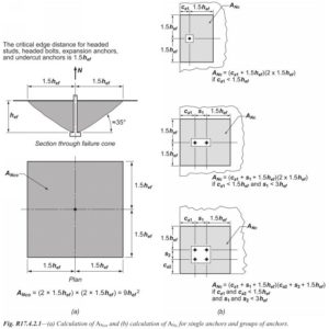
for single and group of anchors can be calculated as per the Fig. R17.4.2.1 excerpt from ACI 318M-14 below:
C. Pull out Strength in Tension
The nominal pullout strength , of a single cast-in, post Installed expansion and post installed undercut anchor in tension shall not exceed:
where:
for an anchor located in a region of a concrete member where analysis indicates no cracking at service load levels, otherwise
D. Concrete side face Blowout Strength of Headed Anchor in Tension (17.4.4)
For a single-headed anchor with deep embedment close to an edge ( ), the nominal side face blow-out strength,
shall not exceed (17.4.4.1):
If for the single headed anchor is less than
, the value of
shall be multiplied by the factor
where
For multiple headed anchors with deep embedments close to an edge and anchor spacing less than
the nominal strength of those anchors susceptible to a side-face blowout failure,
shall not exceed (17.4.4.2):
where s is the distance between the outer anchor along the edge, and is obtained from equation (17.4.4.1) without modification for perpendicular edge distance.
E. Bond Strength of Adhesive Anchor in Tension
The bond strength of adhesive anchor in tension and the design criteria under a shear loading will be published soon. So stay tuned and subscribed to our newsletter for any updates. Tell us about your thoughts! Feel free to leave a comment on the comment form below.
![]()








thank you for your topic. it’s great!!! but how to determine Anchor tension area (Ase,N) and Anchor shear area (Ase,V)???