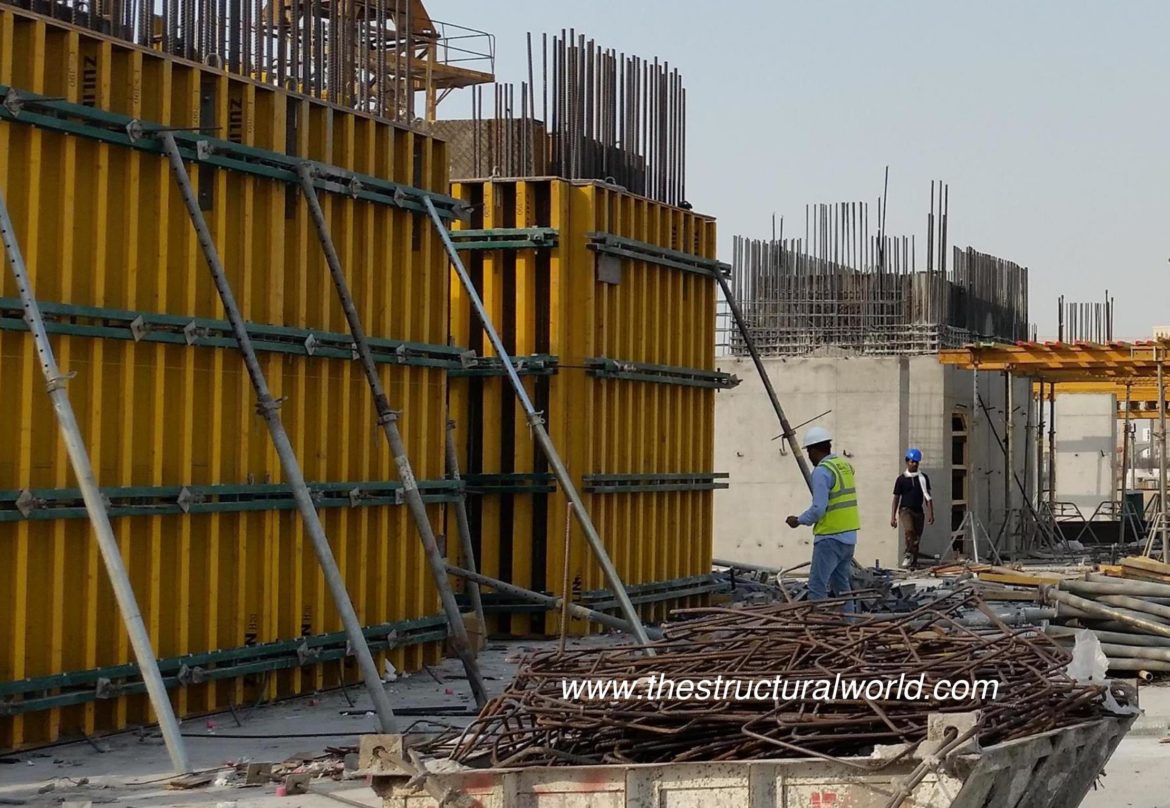
DIAPHRAGM
DIAPHRAGM is horizontal or nearly horizontal system acting to transmit lateral forces to the vertical resisting elements. The term “diaphragm” includes horizontal bracing systems. There are two popular types of diaphragm namely rigid diaphragm and semi-rigid Diaphragm. The RIGID DIAPHRAGM can rotate and it can translate, but cannot deform. The lateral forces will be distributed & redistributed at the subsequent levels based upon the relative stiffness of all the members resisting lateral loads at each level. When applied in software, the beam in the lateral system had no axial force. The SEMI-RIGID DIAPHRAGM used mainly for defines the wind load and give the building the ability to behave as its actual behavior.
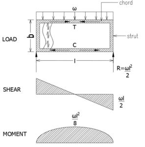
The behavior of horizontal diaphragms is comparable or similar to the behavior of a simply supported, uniformly loaded deep beam as shown in the shearwall below.
The diaphragm resists the bending moment through perimeter elements known as chords.
- The chord forces, which are axial in nature, are the result of resolving the internal bending moment into a force couple with a moment arm of dimension “b”.
- M=C x b or C = T = M / b
- In our building, the shear wall horizontal perimeter functions as the chord. In an all-concrete building, the top plate of the shear wall serves as the chord element.
Internal shear is carried by the slabs.
- In horizontal diaphragms, shear has been found to be nearly uniform across the depth, b.
- It is convenient to express the shear as a unit shear term.
- Shear per unit width: v = V/b.
- The support reactions are transmitted directly to the Shear walls through proper connection detailing.
- Struts are needed when a diaphragm spans over a wall opening that prevents direct transfer of shear to the wall.
The Behavior of Horizontal Diaphragms in Buildings:
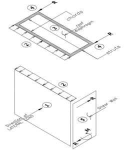
With reference to the figure above, the following description is provided as a review of the basic behavior of a simple shear wall building in response to a lateral load. The elements marked with numbers corresponding to the behavior of the diaphragm in action due to the application of the lateral loads. By which states as follows:
- The transverse applied lateral load is carried to the roof and foundation by the wall which is assumed here to be a vertically spanning element.
- The roof and foundation support the vertically spanning wall and consequently pick up the developed horizontal reactions.
- At the roof level, these wall reactions, turn the load in the roof system, in the plane of the roof. This horizontal element is known as the diaphragm.
- The diaphragm resists the in-plane loads by acting as a large horizontal beam spanning between the supporting end walls that are known as shear walls.
- Properly designed shear walls will then resist the applied diaphragm reaction and transfer the shear load and possible overturning moment to the foundation.
We would love to hear from you. Feel free to share your thoughts and leave your comment below. You can also subscribe also to our newsletter for any updates. Sharing is caring! So don’t hesitate to share this article, I am sure someone out there might need this knowledge.
![]()






So how could we determine the location of a diaphragm in a building and where to put the shear wall?