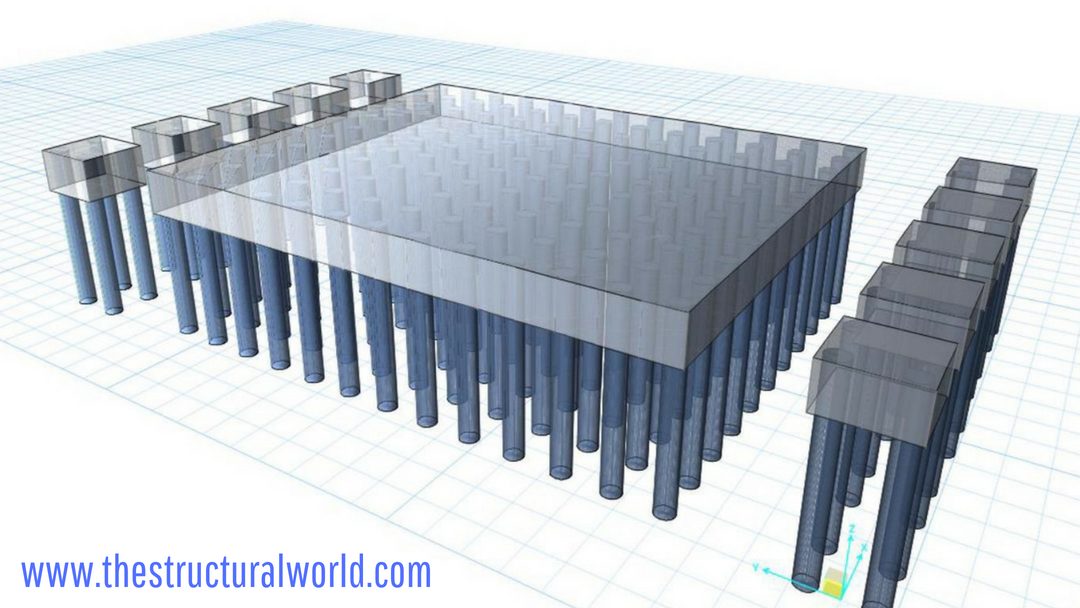
Aside from flexural checks, one of the most important points to consider in the design of the pile cap is the Punching Shear Checks. As we all know, Punching Shear is a concentrated load causing shear stress on the section around the load and this load should be resisted by the structural member from where the concentrated load or the reaction is rested. In punching shear considerations, there are actually two checks to consider in the design of pile caps. One is the punching shear strength of pile cap due to the concentered load of the column and the other is the shear strength of pile caps due to the reactions of a pile or group of piles. Punching shear checks should be taken seriously as structural failures due to punching before it occurs leaves a minimal warning or specifically, no warning at all. As a structural engineer, of course, the safety of the occupants is more important than anything else that is why we need to be very cautious in our design concerning punching shears.
After the geometrical assumptions as tackled in previous article Pile Cap Design Assumptions and Recommendations were made, the design validation using software or manual calculations should be done accordingly. One of the verifications required is to check if the design thickness is adequate to resist the concentrated load or reactions, if not we need to increase the thickness or provide additional shear reinforcements. But, usually, the first thing that comes in the structural designer’s mind is to increase the thickness rather than providing the shear reinforcements, especially if you are designing a pile cap.
This article will be discussing on how to perform a Punching Shear Checks in Pile Caps. It will show you how to consider the punching shear checks using the SAFE program and the punching shear capacity checks as specified by the ACI code.
Punching Shear Check using SAFE model
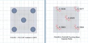
Perhaps the Punching Shear Check is the last step to consider in the design of the pile cap. Let us take a look at the image below an excerpt from a working model. Supposed we had a SAFE model of pile cap already performed the run analysis. For the member to be adequate in punching shear, the ratio of the actual shear stress divided by the capacity of shear stress should be less than one. If the result says otherwise then, our assumed thickness is inadequate and an increase in thickness is required.
In the SAFE interface, click the Display>Show Punching Shear Design and the Punching Shear Capacity Ratios/Shear Reinforcement will be displayed. Let us take a look at a 2500mm thick pile cap supported with 5 numbers of piles in Figure 1. It is noticed in Figure 2 that the capacity ratios due to pile reactions and column loads are less than 1 then our assumed thickness is adequate in punching shear.
Punching Shear Capacity Check as Specified in ACI Code
Although there is a separate approach on how to design the punching shears in detailed, we can verify the above SAFE result using the punching shear capacity check. The capacity of pile cap to resist the punching shear can also be check manually according to ACI 318-14 table 22.6.5.2 Calculation of Vc for two-way shear. The compression force due to column loads and the vertical reaction due to piles in cases of punching check due to column and piles respectively should be less than the value of the following three equations:
Where:
- λ is a modification factor (table 19.2.4.2) for lightweight concrete=0.75 and normal weight concrete = 1.0
- β is the ratio of the long side to the short side of the column, concentrated load or reaction area
- αs can be taken as 40 for an interior column, 30 for edge column and 20 for corner column
- fc’ is the compressive strength of concrete
- d is the effective depth of the section is the distance measured from extreme compression fiber to the centroid of the tension reinforcement
- bo is the two-way shear critical perimeter section measured d/2 from the face of the column or pile
Available spreadsheets for the Design of PILE CAPS for two, three, and four piles can also be used to design. Kindly select the images for more!
PILE CAP Design Spreadsheets
TWO-PILES | THREE-PILES | FOUR PILES |
 |  |  |
We would love to hear from you! Share your thoughts on the comment form below. Feel free to share this article, subscribe to our newsletter and follow us on our social media pages.
![]()




thats good for two way punching shear, what about one way shear/beam shear check specially when the distance between the piles is kept 2.5-3.0 times dia of the piles?
I reckon this check has to be made separate and cannot be checked in SAFE?
Thanks
Regards
Omar Hayat, CPEng
That is correct Mr. Omar, the one-way shear/beam shear check should be done separately as well.
Hi
Nice blog
Isn’t punching shear check non-relevant when using the strut-and-tie approach for pile caps design ?
Regards
Marius B.
The strut and tie method is applicable for simple arrangements like 4 pile group and assumes a rigid pile cap. With the current designs which have 10-12 piles strut tie method not applicable.