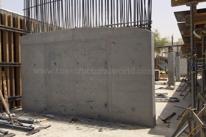
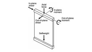
One of the main structural parts of a building structure is the shear wall. Shear Wall is a vertical structural element used to resist the lateral forces that are usually due to the wind and seismic loads. These forces are acting in the plane of the wall by the cantilever action where the bending deformation governs if slender walls are concern and a truss action for short walls where the shear deformation governs. Refer to the below figure Fig. R11.4.1.3 of the ACI 318-14 for the In-plane and out of plane forces in walls.
This article will discuss the elements of shear wall design according to ACI 318-14 that categorizes in the following:
- Factored Axial Force Pu, moment Mu and shear Vu
- Wall Shear Reinforcement Requirements
- Boundary Elements / Boundary Zones
1. Factored Axial Force Pu moment Mu and Shear Vu
According to Section 11.4.1.4 of ACI 318-14 walls shall be designed for eccentric axial loads and any lateral or other loads to which they are subjected. Walls shall be designed for the maximum factored moment Mu that can accompany the factored axial force Pu at a given eccentricity and shall not exceed фPn,max, where Pn,max is equal to 0.80Po (table 22.4.2.1). Interpreting in an equation:
Pu < фPn,max = ф 0.80Po where Po=0.85fc’ (Ag-Ast) +fyAst (22.4.2.2)
where:
- Ast: the total area of nonprestressed longitudinal reinforcement.
- Ф: 0.65 (table 21.2.2)
- fy: yield strength of rebar
Mu shall be magnified for slenderness effects in accordance with the 6.6.4, 6.7 or 6.8. and factored shear Vu shall be designed for the maximum in-plane and out-of-plane Vu.
2. Wall Shear Reinforcement Requirements
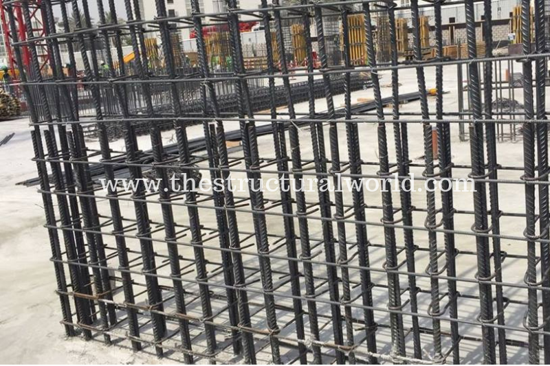
Both horizontal and vertical shear reinforcement is required for all walls. The distributed reinforcement is identified as being oriented parallel to either the longitudinal or traverse axis of the wall. For vertical wall segments, the notation used to describe the horizontal distribution is and the notation used to describe the vertical distribution is
. As per section 11.6.1., if in plane Vu ≤ 0.5 ФVc, minimum
and
and shall be in accordance with:
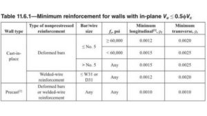 If in-plane Vu ≥ 0.5 ФVc, (a) and (b) below should be satisfied:
- (a)
shall be at least greater of the value calculated by Eq 11.6.2 and 0.0025, but need not to exceed
in accordance to with Table 11.6.1.
≥ 0.0025 + 0.5(2.5-hw/lw)(
-0.0025) eq.11.6.2
- (b)
shall be at least 0.0025
3. Boundary Element / Boundary Zones
Another category in shear wall/wall design is to determine the area of boundary element. Boundary Element is a portion along wall and diaphragm edge, including edges of openings, strengthened by longitudinal and transverse reinforcement. It is a zone in a wall wherein a confinement reinforcement is needed. A different approach in the determination of boundary zones is available according to the different code requirements. Detailed article regarding the determination of boundary element or boundary zone will be tackled on a separate article-Determination of Boundary Zone.
A Shear wall/wall design using an ETABS program will be published soon. So stay tuned by subscribing to our newsletter. We’d love to hear from you, don’t hesitate to leave your comment below and share this article. You can also follow us on our social media pages.
[DISPLAY_ACURAX_ICONS]



I was working on building a wall like this for one of my customers and needed to do some research for it. I stumbled across this page and I just wanted to say thanks for sharing the great information.
You have shared really an informative content. Keep posting!