Overview
In ETABS design of shear walls or retaining walls, the programs calculate and report the required area of steel for flexure and shear based on the applied and defined load combinations. During the modeling process, the walls should be modeled as shell elements. And before the program does its tasks, the designer should define the wall labels and assign them as pier or spandrel. The pier/spandrel labeling should perform to get the design forces and reinforcement requirements. The right labeling should be imposed to ensure realistic output results. Further details have been explained in succeeding paragraphs.
Assigning Pier/Spandrel Label
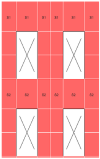
A wall pier and a wall spandrel can consist of a combination of shell elements and frame elements. However, modeling it as a shell element provides more flexibility and accuracy in the design analysis and results. To extract the wall forces and to design and check the wall, the designer should define the pier labels and spandrel labels at first. You can control the pier and spandrel labels assignment accordingly. For example, if you want to get design forces of one particular part of the wall, then you can assign a pier or spandrel label on that portion only. Nevertheless, Figure 01 and Figure 02 below show the recommended pier and spandrel labeling respectively.
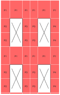 Figure 01 Recommended Pier Labeling Scheme
In Figure 01, assigned piers are always associated with the story level directly above them. Hence, in Figure 01, the upper-level wall piers are associated with the topmost level and the lower level wall piers are associated with the lower level. Because the wall piers are associated with story levels, wall pier labels can repeat at different levels, as shown in the figure. Wall pier design is performed at the top and bottom of each pier. Thus, for wall pier P2 at the topmost level, the design is performed at the top and bottom of the door opening. No design is performed near the mid-height of the door opening because the design is done at the top and bottom of the wall pier, not the top and bottom of each area object that makes up the wall pier.
Figure 02 Recommended Spandrel Labeling Scheme
In Figure 02, the upper wall spandrel label S1 is associated with the topmost level and the lower S2 is associated with the lower level. Because the wall spandrels are associated with story levels, wall spandrel labels can be repeated at different levels. It is noticed that the topmost wall previously labeled as P1 has been labeled also as S1 for spandrel, same with the lower level labeled as S2. This is to capture the forces and designed as both spandrel and pier whichever governs. By the way, spandrels are usually located above the opening, but during the design process, it is the author recommendation to assign the wall above the openings as all spandrels to capture the forces and areas of reinforcements including the links to be designed as coupling beam or link beams.
How to Assign Pier/Spandrel Labels in ETABS
To Assign Pier labels In ETABS, we need to define pier labels first as mentioned on the overview. In ETABS interface, go to Define>Pier Labels and assign pier name (P1) and click the “add new name” button. On the other hand, to assign spandrel labels, go to Define>Spandrel Labels assign spandrel name (S1) and click add “new spandrel name” button. After defining pier and spandrel label, select the wall to assign the pier or spandrel as per the recommendation in Figure 01 and Figure 02 respectively. Check out our video below on how to define and assign pier and spandrel in ETABS. You can also subscribe to our channel for more ETABS modeling and design techniques.
Application:
After assigning the pier and spandrel labels as explained above, the program performs the following design, check, and analysis procedure in accordance with the specified code requirement:
- Design and Check of concrete wall piers for flexure
- Design of concrete wall pier for shear
- Design of concrete shear wall spandrels for flexure
- Design of concrete shear walls for shear.
The following are the available ETABS design and check option for shearwall/retaining wall design. Each of its descriptions will be published in another article. Stay tuned!
- Simplified C & T- Design of planar walls
- Uniform Reinforcement
- General Reinforcing
Reference: CSI ETABS
What do you think about this article? Tell us your thoughts! Leave a comment on the section below. Subscribe to our newsletter to be updated with the latest posts or follow us on our social media pages on the below icons.
![]()





Pingback: How to Design Spandrel or Coupling Beams in ETABS | | The Structural World
Thank you so much, but I’m wondering, why do we have to assign the pier and spandrel labels to the same exact shell element? this is a little bit confusing to me