In the previous article, Scaling of Base Shear Results of Static and Dynamic Analysis we have learned about the principle why do we need to scale the base shear results obtain from dynamic analysis to reduce or match of the base shear results that is determined from the static force procedure. The international codes such as UBC-97 and ASCE 7 are adopted by most countries in determining such procedure called the Static and Dynamic Lateral Force Procedure.
There are lots of available structural soft wares that can perform the modal response spectrum analysis of high rise projects; one of them is through the help of ETABS. The question is how to perform the actual scaling of base shear using ETABS to match with the static base shear? Well, stick around as this article will guide you how the scaling is being performed in ETABS using UBC-97.
Did you know that there are two methods or options to scale base shear in ETABS? These two approaches on how to scale the base shear are demonstrated in the succeeding examples.
How to Scale Base Shear in ETABS
In this article, the author assumed that an ETABS model is already been set up and the necessary seismic parameters are already been specified. Nevertheless, a video was published on our YouTube channel for further reference. You can subscribe to our channel for more videos regarding structural modeling techniques and tips.
Scale Factor
The scale factor has units of acceleration which is length/seconds2 and that its value will change as you change the units in the model. Hence, ETABS assumes that the response spectrum functions are unitless and that the scale factor converts them into the appropriate units. So the use of a scale factor equal to 9.81 can convert the response spectrum into acceleration (m/s2).
If you are scaling the response spectrum to match with the static analysis results, you need to input the computed scale factor and specified it under response spectrum cases in ETABS. This is to convert the spectrum into required units and for the base shear to scale it to an appropriate level.
Method 1:
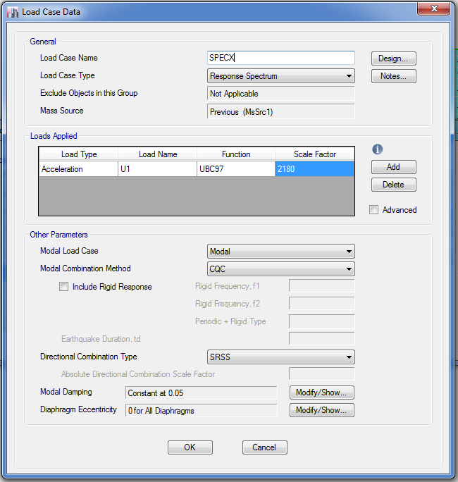
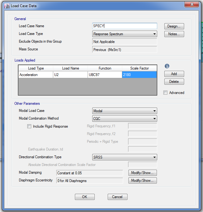
Perhaps method 1 is the most widely used procedure used by engineers on how the base shear is being scaled. In this option, an initial scale factor is assigned in scale factor in each load cases as shown in figure 1.1 below. An initial scale factor using the formula g/RI shall be used. This is to convert the spectrum into mm/sec2.
Initial scale factor: g/RI
where:
-
- g: gravitational acceleration equals to 9810 mm/sec2
- R: Overstrength, Coefficient equals to 4.5 in this example or as per UBC 97- Table16-N
- I: Importance factor equals to 1.0 in this example
Thus, Initial Scale Factor: (9.81m/sec2/4.5×1.0) x 1000mm = 2180
Figure 1.1: Response Spectrum Cases for X and Y Direction
After the initial scale has been set, run the model and extract the static and dynamic base shear generated after the analysis as shown in Table 1.1 below.
Table 1.1: Reactions for Static and Dynamic Base Shear after the Initial Run
Substitute the values of Static Base Shear (EQx and EQy) and Dynamic Base Shear (SpecX and SpecY) using the formula below to use as the final scale factor:
SpecX= (Static/Dynamic) x Initial Scale Factor
SpecY= (Static/Dynamic) x Initial Scale Factor
Using the formula above the results for the final scale factor is tabulated below:
Table 1.2: Tabulated Table for Final Scale Factor Calculations
Unlock the model and input the final scale factor in SpecX and SpecY load cases as calculated. Run the model once more to be used as your final ETABS model to proceed with the design proper.
To check if we successfully scaled the model, the static base shear should match with the dynamic base shear as highlighted in the table below.
Table 1.3: Matched Static and Dynamic Base Shear using Method 1
Method 2:
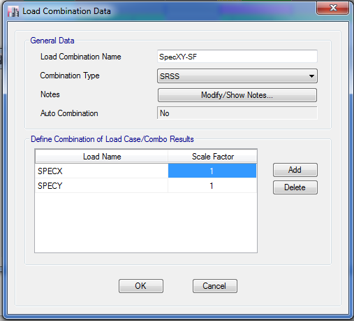
In method 2, we don’t need to re-run the model after assigning the initial scale factor in response spectrum load cases. Instead, we will create a load combination, SpecXY and input the calculated scale factor in the corresponding combination. This method is advantageous for heavy models that need time to run. As this method does not require any additional analysis since we can easily modify it anytime in the load combination itself even after the analysis.
Figure 2.1: Load Combination for Response Spectrum
This is how it goes: Set up the load case data for response spectrum similar in Figure 1.1 of Method 1 explained above. Run the Model and extract the static and dynamic base shear as shown in Table 2.1.
Table 2.1: Static and Dynamic Base Shear
Substitute the values of Static Base Shear (EQx and EQy) and Dynamic Base Shear (SpecX and SpecY) using the formula below to use as the final scale factor:
SpecX= (Static/Dynamic)
SpecY= (Static/Dynamic)
Using the formula above the results for the final scale factor is tabulated below:
Table 2.2: Tabulated Table for Final Scale Factor Calculations
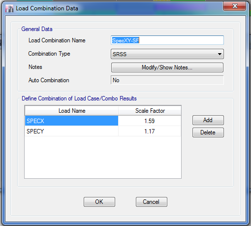
The ratio of static to dynamic base shear as per the calculation presented in Table 2.2 has to be inputted as a scale factor in Figure 2.2 below.
Figure 2.2: Assignment of Response Spectrum Scale Factor
After modifying the scale factor as per the calculation presented in Table 2.2, we don’t need to re-run the model and we can proceed to design procedure accordingly. To check whether we successfully scaled the model, let us investigate the base shear reactions. If the static and dynamic base shear matches with each other, then the scaling is successful as shown in Table 2.3.
Table 2.3: Matched Static and Dynamic Base Shear using Method 2
What do you think about this article? Which method above did you prefer? Tell us your thoughts, leave a message on the comment form below. Leave a comment on the section below. Subscribe to our newsletter to be updated with the latest posts or follow us on our social media pages on the below icons.
![]()

