Our previous article, CSI SAFE Slab Considerations Prior to Analysis, discusses the points required in modeling a slab using CSI SAFE before performing slab analysis and design. To deliver a complete slab design procedure using SAFE software, the designer should consider and exercise the three major post-analysis checks accordingly.
The below-mentioned design considerations are important points that have to be checked by the designer once the slab model has been analyzed and all the considerations according to the previous article has been completed.
1. Check for Long Term Deflection
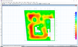
After the run-analysis of the slab, the designer’s first thing to check is if the slab satisfies the long term deflection. The long term deflection should not be less than L/240 according to ACI code and ideally not more than 24 millimeters. To set the model for a long term deflection analysis, you can refer to our previous article, Long Term Deflection Analysis using SAFE. Once the load cases and load combinations have been set for a long term deflection analysis, check the model by going to Display>Show Deformed Shape, scroll down the Long Term Deflection Combinations that previously set and hit apply. To check the long term deflection values, navigate your cursor to the contour provided by the analysis.
If in case the results of long term deflection are not satisfactory, you can either increase the slab thickness or provide a beam just to lessen the excessive deflection on the entire area or on the area of slab being checked.
Figure 1: SAFE Cracked Deformed Shape for Long Term Deflection
2. Check for Punching Shear Ratios
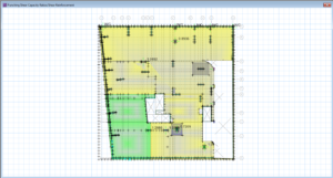
The safe and sound slab should also be satisfies punching shear. To check this in the model, go to Display>Show Punching Shear Design. Investigate the column supports for punching shear capacity ratios. The slab is safe for punching shear if the capacity ratios of each column support are less than unity. Punching shear links or even a drop panel is needed for that column support with values of more than one, which needs to be designed accordingly. To check for columns that are modeled as wall properties, draw design strips along X and Y direction and investigate the shear and moment output results of the design strips needed in punching shear checks.
Figure 2: SAFE Punching Shear Capacity Ratios
3. Slab Design
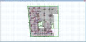
Once the above two checks have been satisfied, the designer can proceed to the slab design-proper. To display the reinforcement results needed in the slab go to Display>Show Slab Design and the slab design window will appear. From there you can input the main mesh reinforcement of the slab for top and bottom and the program will show you the area of the extra top and bottom reinforcement and the location from where it will place. Refer to our previous article, how to interpret the SAFE reinforcement for your reference.
Figure 3: SAFE Extra Reinforcements for Top and Bottom Additional to Main Mesh
Provide Mark-Ups
The locations of the top and bottom reinforcement as a result of the SAFE design should be marked up by the designer in the plan/drawing. These markups will be handed over to the structural draftsman for the detailing process and should eventually be check by the designer to complete the design.
What do you think about this article? Any considerations that we missed? We love to hear from you! Leave a message in a comment section below. You can also follow, like and subscribe to our social media pages below to be updated with the latest posts.
[DISPLAY_ACURAX_ICONS]




Pingback: CSI SAFE's Slab Design Considerations Prior to Analysis | | The Structural World
very interesting article. i am contented reading this lovely article. i hope to do more about different structural softwares.