When using the ETABS software as your tool for analysis and design in your project on-hand, you must equip with thorough knowledge and understanding in every aspect and stage from modeling to analysis to design of each structural member. Each stage has its own technique and guidelines in order to make our ETABS model as accurate as possible and free of warning and error messages.
You probably knew the different considerations and techniques when modeling using ETABS as well as knew the analysis guidelines and checklists when doing the pre and post-analysis procedures. Well, this time we will tackle the Design and Check procedure options in ETABS particularly in column design. What are the design considerations to look at in order for us to be sure that the structural members that we are designing are passing and no single structural member fails?
There are two options to design the columns in ETABS. We can either use the “Reinforcement to be Checked” and “Reinforcement to be Designed” option. Reinforcement to be checked option is used when the designer inputs the number of rebars and the program will check if the inputted rebar is sufficient enough to carry such load. On the other hand, when using “Reinforcement to be Designed”, the program will generate the area of rebar needed in that column for the designer to interpret into how many numbers of rebar required.
Of the two options in column design, this article will guide on how to do it using the “Checked” option.
How to Design Column using Reinforcement to be Checked Option:
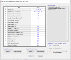
After the model has been run and analyzed, select all the columns or the column in consideration by going to Select>Properties>Frame Section and select all the properties of columns. Prior to Design/Check of columns, set the design preferences accordingly by going to Design>Concrete Frame Design>View/Revised Preferences. In this window, you can set the design code to use and other parameters that you wish to modify.
Figure 01: View/Revised Preferences Window
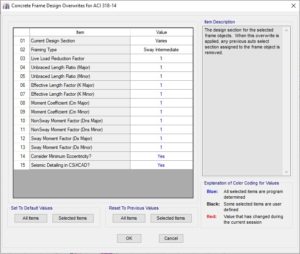
Go to Design>Concrete Frame Design>View/Revised Overwrites to modify the modifiers required in the design.
Figure 02: View/Revised Preferences Window
Verify that all the members (columns) have passed the designed check by going to Design>Concrete Frame Design> Verify All Members Passed. Once all the members passed the design check, go to Design>Concrete Frame Design>Start Design/Check to design the columns accordingly.
Column Design Results
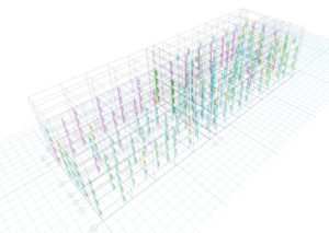
Once the Start Design/Check has been finished, you can see immediately the columns that are failing that is if you see columns in red color. However, this doesn’t mean that columns that are not red colors are already passed the design. You need to investigate each column if it fails in flexure and shear. Basic modifications in columns should be made if found not satisfactory. More steel reinforcements are required when the columns are failing in flexure and increase in thickness if it fails in buckling.
Figure 03: Column Design Results
Column Design Summary
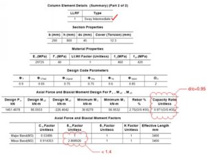
Further checking of the column should be done individually. This is to make sure that no single column is failing. You can do this by right-clicking on the column in considerations and press the summary button. Scroll down to page 2 and verify that the design capacity ratio (d/c) is less than 0.95 and the non-sway moment magnification factor, δns should be less than 1.4. Provide additional steel reinforcements and increase the thickness of the column if the d/c and δns are not satisfactory respectively.
Figure 04: Column Summary Results Showing a Failing Column
What do you think about this article? We love to hear from you! Leave a message in a comment section below. You can also follow, like, and subscribe to our social media pages below to be updated with the latest posts.
![]()

