The previous article “Basics of Load Calculations in Structural Design”, shows us the load path and how the assigned load was distributed in beams. These beams should resist the calculated loads for a safe and sound design. Surely there are lots of methods how to design a beam with the help of other sophisticated software. But in this article, we will show you the easiest way to a beam design by far.
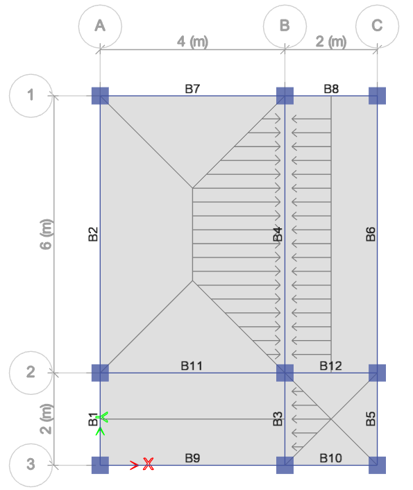
For example, let’s take a look at the beams B3 and B4 in the Figure below.
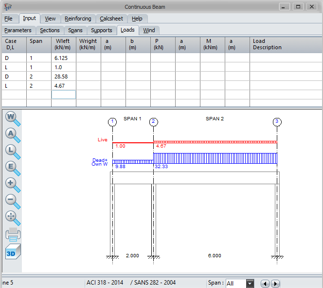
According to our previous calculation, with reference to our previous article, these beams have design loads as shown below. We will start from there.
- For beam, B3:
- DL= 6.125 kN/m
- LL= 1.0 kN/m
- For beam, B4:
- DL= 28.58 kN/m
- LL= 4.67 kN/m
Perhaps the fastest or easiest way to design a beam is through the aid of structural software and a spreadsheet. In this example, we design our beam using Prokon beam design software. Let’s get started.
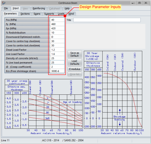
1.0 Upon setting our desired design code, we input our parameters accordingly. The screenshot shows the design parameters; we use in this design.
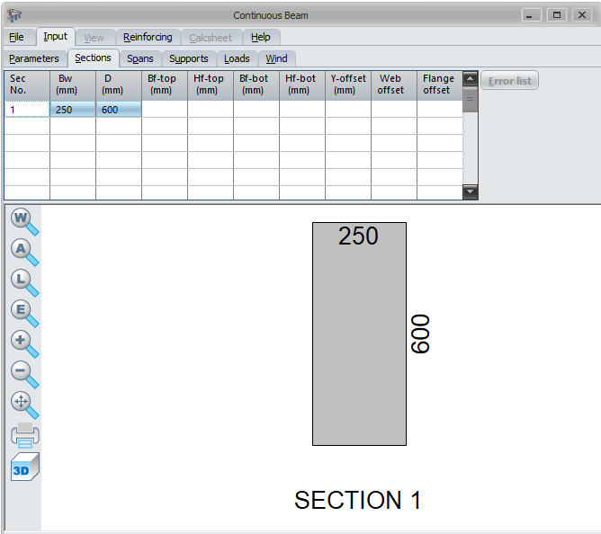
2.0 On the section tab, we going to define the beam size, width, and depth of 250×600.
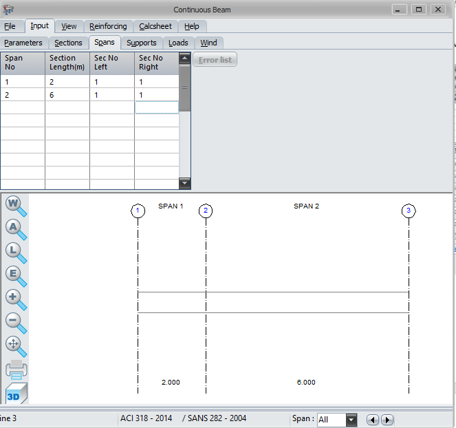
3.0 On the Span tab, we will input the length of the beams accordingly and the section number that is previously defined.
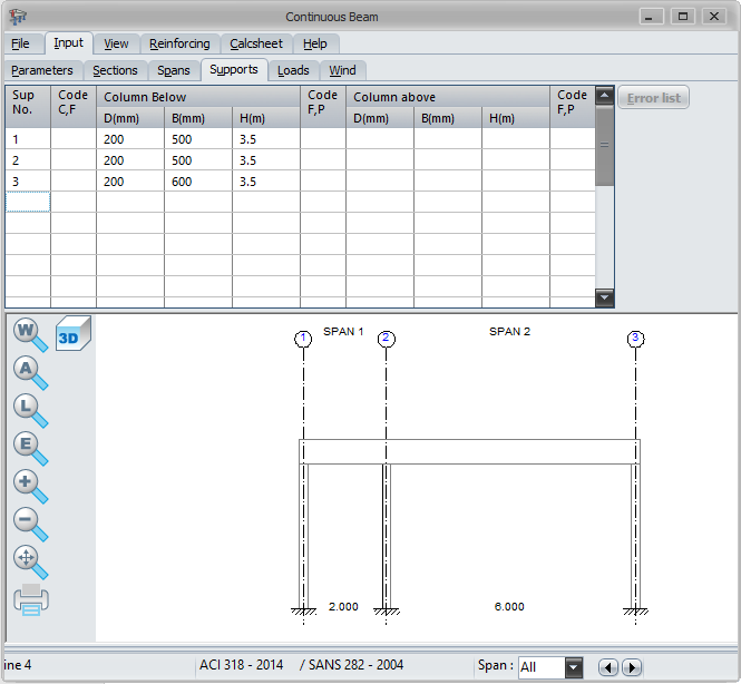
4.0 We will define the support of our beam on the Support Tab, depending on your plan we can define either cantilever(c) or fix (f). Also, the column support dimension will be defined here as shown. We don’t have a cantilever beam in this example, so it’s not applicable.
5.0 Design Load Inputs. Here, we going to input the design loads, DL and LL that we previously calculated. Note that the beam’s self-weight is automatically added by the software in this input.
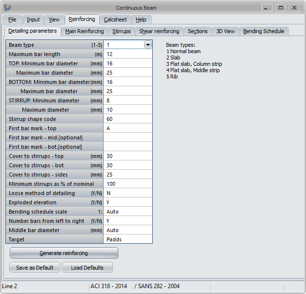
6.0 On reinforcing tab as per the figure below, we input detailing parameters as shown and press “Generate reinforcing”.
The required rebar will be generated as shown. From here we interpret the results into beam schedule or beam details. Note that before doing so, we see to it that the beam deflection is less than the allowable deflection for a safe design.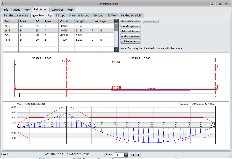
The design results such as the stirrups reinforcements and spacing will be indicated as well upon pressing the “stirrups” tab. We can also print the deisgn calculations on the “Calculation” tab.
The result of the reinforcements shall be reflected in beam detail or schedule of beam to be provided in the drawing.
The information about the software is available here https://www.prokon.com/downloads/
What do you think about this article? Let us know your thoughts and comment down below. You can also follow, like, and subscribe to our social media pages below to be updated with the latest posts.
![]()

