After establishing the design loads of the proposed project, the next thing to consider is to determine the appropriate design load combinations. Generally, load combination is composed of individual loads, i.e. dead load superimposed dead loads and live loads that are combined together to come up for a strength design and allowable stress design. By the ASCE7-10 (section 1.2.1) code definition, strength design is the product of the nominal strength and a resistance factor while the allowable stress design is composed of computed forces produced in the member by factored loads that shall not exceed the member design strength.
Each design code and standards had a different recommendation when it comes to loading combinations. In this article, we will emphasize the design load combinations as recommended by ASCE7-10 for basic design load combinations with the touch of UBC97 seismic load combinations. Let us bear in mind that the use of design load and load combinations is depending on the approved code and standards authorize by your local authority having jurisdiction.
Before we proceed into the lists of load combinations, let us take a look at the following symbols used:
- Ak= load or load effect arising from extraordinary event A
- D= dead load
- Dt= weight of ice
- E= Earthquake Load
- H= lateral earth pressure load
- L= live load
- Lr= roof live load
- R= rain load
- S= Snow load
- T=self-straining load
- W= wind load
- Wi= wind on ice
LOAD COMBINATIONS according to ASCE7-10
According to ASCE7-10 section 2.3.2, buildings and other structures, components, and foundation shall be designed so that their design strength equals or exceeds the effects of the factored loads in the following combinations. These are also known as ultimate load combinations:
- 1.4D
- 1.2D + 1.6L + 0.5(Lr or S or R)
- 1.2D + 1.6(Lr or S or R) + (L or 0.5W)
- 1.2D + 1.0W + L+0.5(Lr or S or R)
- 1.2D + 1.0E + L +0.2S
- 0.9D + 1.0W
- 0.9D + 1.0E
*Usually, D can be taken as the dead load in addition to the superimposed dead load (D+SDL) and we can omit the loads that we are not using. Like for example, if we don’t have a snow load on our area, of course, it is acceptable not to consider it in our load combinations.
According to ASCE7-10 section, 2.4 combining nominal loads using allowable stress design are as follows. This is also known as service load combinations.
- D
- D + L
- D + (Lr or S or R)
- D + 0.75L + 0.75 (Lr or S or R)
- D + (0.6W or 0.7E)
- D+ 0.75L + 0.75(0.6W) + 0.75(Lr or S or R)
- D+ 0.75L + 0.75(0.7E) + 0.75S
- 0.6D + 0.6W
- 0.6D + 0.7E
LOAD COMBINATIONS according to UBC-97
According to UBC-97 section 1612 (1612.2.2.1) Basic Load Combinations is as follows where strength design is used, structures and all portions thereof shall resist the most critical effects from the following factored load combinations or the ultimate load combinations:
- 1.4D : (12-1)
- 1.2D + 1.6L +0.5 (Lr or S) : (12-2)
- 1.2D +1.6 (Lr or S) + (f1L or 0.8W) : (12-3)
- 1.2 D + 1.3W + f1L + 0.5 (Lr or S) : (12-4)
- 1.2 D + 1.0E + (f1L + f2S) : (12-5)
- 0.9D ± (1.0E or 1.3W) : (12-6)
where:
f1= 1.0 for floors in places of public assembly, for live load in excess of 100 psf (4.9kN/m2), and for garage live load.
= 0.5 for other live loads
f2= 0.7 for roof configurations (such as saw tooth) that do not shed off the structure)
= 0.2 for other roof configurations.
When allowable stress design (working stress design) is used, the following are the load combination to consider. This is also known as service load combinations.
- D : (12-7)
- D + L + (Lr or S) : (12-8)
- D + (W or E/1.4) :(12-9)
- 0.9D ± E/1.4 :(12-10)
- D + 0.75 [L+ (Lr or S) + (W or E/1.4)] :(12-11)
Special Seismic Load Combinations has to consider as well for both allowable stress design and strength design in accordance to UBC-97 section 1612.4 as follows:
- 1.2D + f1L + 1.0Em :(12-17)
- 0.9D ± 1.0Em :(12-18)
Earthquake Loads and Modelling Requirements:
In accordance with UBC-97 Section 1630 (1630.1.1) Structures shall be designed for ground motion producing the structural response and seismic forces in any horizontal direction. The following earthquake loads shall be used in the load combinations set forth in section 1612.
E = ρEh +Ev : (30-1)
Em = ΩoEh : (30-1)
where:
ρ = Redundancy factor, usually taken as 1.0 and by the formula:
![]()
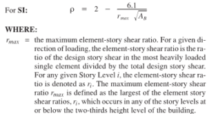
Eh=the earthquake load due to base shear, V.
Ev= ±0.5CaID to the dead load effect, D, for Strength Design, and may be taken as zero for Allowable Stress Design
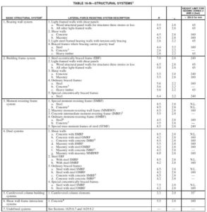
Ωo= seismic amplication factor as specified on TABLE 16-N below:
Wind Drift Load Combinations
Wind drift can be check as per load combinations specified in the ASCE7-10 commentary (CC-3) as:
1.0D + 0.5L + 0.7W
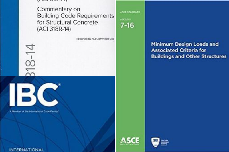
The above load combinations are based on ASCE7-10 and UBC-97. The IBC code has also a recommended load and load combinations, grab your copy here. The uses of these codes are depending on the approved standard set by the authority having the jurisdiction in your location.
What do you think of the above this article? Tell us your thoughts! Leave your message in the comment section below. Feel free to share this article, subscribe to our newsletter and follow us on our social media pages.
![]()





Pingback: ETABS CHECKLISTS : - Design Integrity Blog
I’m trying to design a structural frame for a piece of vibrating equipment. This is the first time that I’ve encountered dynamic loading outside of seismic (which has its own very well-defined and quite elaborate rules) that potentially govern the design, and it’s not clear how to handle it. I note that the very first entry in the list of loads in ASCE 7-16 Section 2.2 is “A-sub-k” which is defined as “load or effect arising from extraordinary even A”, which would seem to suit my purpose exactly. Except there is no load combination where “A-sub-k” appears in either section 2.3 or 2.4. The commentary is utterly silent on the subject. So how do you properly account for this load effect?